I got the first set of printed circuit boards back from ExpressPCB.com. Each of these boards contains 64 of the contact wetting circuits described earlier, so one board is needed for each manual, plus one more for the pedals. The drawknobs use reed switches and therefore don’t need this treatment, but the pistons, toestuds and couplers all do, so it will take nine of these boards to outfit the console.
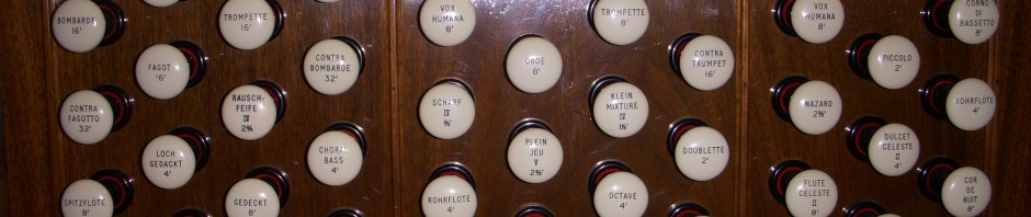
A plain board,

and a populated one. Because of the high degree of regularity on this board, I opted to save $100 or so by omitting the silk screen and solder mask layers. That’s why they aren’t the usual green color. Thanks to my seven-year-old, James, for bending all the resistor pins just right. He doesn’t realize there are several hundred more to do later!

Each key circuit, when activated, consumes nearly 1.5 watts. I’m using 2-watt resistors and 2-watt zener diodes, which is overkill, but excess capacity begets reliability. Besides, I like overkill. The resistors take most of the power, so they get too warm to touch when a key is held down for a minute or more. I soldered them on vertically with air space all around to maximize their ability to dissipate heat (it also made for smaller boards, thus reducing their cost). By weighting a few keys down, I did a 20-minute burn test on the breadboard pictured earlier with no adverse effects. (If it starts smoking, it doesn’t pass the burn test.)
I did some profiling on the microcontroller code, and with a little hand optimization, I’m now scanning the address space of six of these boards (enough for all the pedals & manuals) and applying the inputs to the aforementioned key state machines in about 550 microseconds. Since my design goal is to scan this set of inputs every millisecond, that means I’m using about 55% of the available CPU cycles. Assuming I don’t have to slow down the address & data busses when they are loaded with 15-20 I/O boards, that should leave more than enough cycles to process the slower elements of the console (drawknobs, MIDI traffic, etc). All the digital stuff is CMOS, which has very high signal fanouts, so I’m not expecting a problem. A less attractive fallback plan would be to split the design into two CPUs, one for scanning and MIDI output, and the other for handling MIDI input and driving the solenoids, but that would introduce split-brain issues and make it more difficult to work around limitations of Hauptwerk version 2 (if there are any).
I also validated the MIDI IN and MIDI THRU circuits, completed the CPU board layout, and ordered a few copies. I hope to bring the code up on the CPU board in a week or so.
